Q11: How to choose the right MFC range?
A: For best performance, keep the typical operating point within 30%–80% of full scale, and avoid operating below 10% F.S. for extended periods. An oversized range reduces accuracy at low flow rates, while an undersized range limits adjustment margin.
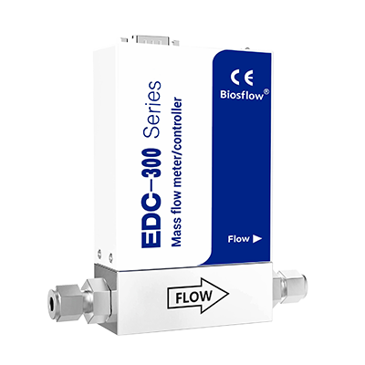
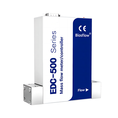
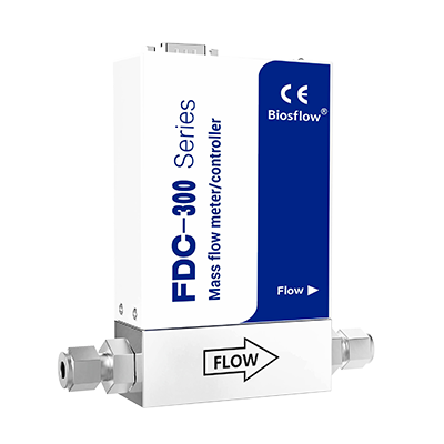
Q12: Differences between FDC-320 / EDC-320 / EDC-325
1. FDC-320 – Mass Flow Controller
- Cost-effective solution with performance comparable to Bronkhorst and Brooks.
- Competitive pricing and short delivery time (3–4 weeks).
2. EDC-325 – Enhanced Mass Flow Controller
- Higher accuracy and wider range ratio (100:1) compared to the FDC series (50:1).
- Features a large touch screen for direct operation and real-time data display (no additional software or equipment required).
- Supports over 40 gas switching functions and gas customization functions.
- Supports direct power plug-in functionality.
3. EDC-320 – Enhanced Mass Flow Controller
- Similar to the EDC-325 but without the touch screen and gas switching functionality.
- All other features remain the same.
Q12: MFCs without a screen can be controlled via analog signals 0–5V / 4–20mA or digital communication RS-485. MFCs with a screen can be operated directly via the touch screen to set flow rates. In addition, we can also provide control boxes and software to control the MFC.
Q12: For mixed gases, the proportion of each component must first be known. Different gases have different conversion factors. The mixed gas factor is calculated based on the specific component factors, and then the model is selected according to the flow rate. For example: if the customer has a mixed gas of 80% N₂ + 20% CO₂ with a total flow of 1000 sccm, the mixed gas factor is 0.8×1.00 + 0.2×0.74 = 0.948. When calibrated with N₂, the flow rate is 1000/0.948 ≈ 1055 sccm. The model is selected based on the maximum flow rate of 1055 sccm.
Q13: What do accuracy, repeatability, linearity, and response time mean?
A: Accuracy measures the deviation between the measured value and the true value. In contrast, repeatability reflects the stability under the same conditions over multiple measurements. Moreover, linearity describes the relationship between output and flow rate. Finally, response time indicates how quickly the flow rate reaches the target after a setpoint change.
Q14: What working pressure differential does an MFC require?
A: Thermal MFCs generally require a certain valve pressure differential for proper control, commonly from several tens of kPa to several hundred kPa. Low-pressure-differential models can achieve lower values; please refer to the selection table for details. Our MFCs support a floating pressure differential of 3–100 bar when maximum flow rates stay within 10 L. If your maximum flow rate is up to 100 L, the inlet pressure ranges from 3 to 20 bar, and we also provide a floating pressure differential. For low-flow applications, we can achieve a minimum pressure differential of only 0.05 bar. Should you need specific details, please contact our sales representative, Alexa, at Alexa@biosflow.com.
Q15: How to choose maximum pressure resistance and leak rate?
A: Choose based on gas source pressure, system pressure, and safety requirements. High-purity or hazardous gases usually require higher pressure resistance and lower leak rates, such as helium leak detection specifications.
Q16: What connection options are available?
A: Common options include VCR, tube fittings, flanges, NPT, G1/4, etc. In addition, high-purity applications commonly use VCR and metal seals, whereas general industrial applications can use tube fittings or threads.
Q17: How to choose sealing materials?
A: Common materials include Viton, Buna-N, EPDM, Kalrez, PTFE, metal seals, etc. In addition, because corrosive gases, high-purity gases, and high-temperature applications demand specific material properties, you need to choose the corresponding sealing material accordingly. For more details, please visit the TECHNICAL & SERVICE page, where you can download the gas factor and sealing material table.
Q18: How to choose between analog and digital communication?
A: Common analog signals include 0–5V, 0–10V, and 4–20mA, whereas common digital communication protocols include RS485/Modbus, Profibus, DeviceNet, EtherCAT, Profinet, EtherNet/IP, etc. In addition, for highly automated systems, we recommend digital communication.
Q19: How to choose between normally closed and normally open valves?
A: Normally closed valves close when power is off, which is safer and suitable for most gases; normally open valves open when power is off, suitable for occasions requiring continuous gas flow or special processes.
Q20: What are multi-gas calibration and conversion factors?
A: We usually calibrate MFCs with N₂. However, if you switch to another gas, you can use a conversion factor to estimate the flow rate; however, this will reduce accuracy. Therefore, for high-accuracy requirements, we recommend calibrating with the actual gas. For the gas factor table, please visit the TECHNICAL & SERVICE page, and we can also provide a link if needed.
Q21: Can ordinary MFCs be used for corrosive, toxic, or flammable gases?
A: Not recommended. In such cases, you need to select corrosion-resistant wetted materials, special seals, purge structures, and explosion-proof or intrinsically safe certifications; moreover, you must confirm the on-site safety regulations. Therefore, please confirm the details with our sales team, and they will recommend a suitable model for you.
Q22: Does an MFC require explosion-proof certification?
A: When you use an MFC in flammable or explosive environments, you may need to obtain certifications such as ATEX, IECEx, intrinsically safe Ex ia, or flameproof Ex d. However, ordinary MFCs usually do not provide explosion-proof protection.
Q23: Are there installation orientation requirements for MFCs?
A: For most models, install the MFC horizontally and follow the arrow direction. Also, keep it away from vibration, high temperatures, and strong electromagnetic interference.
Contact Us
Related Products