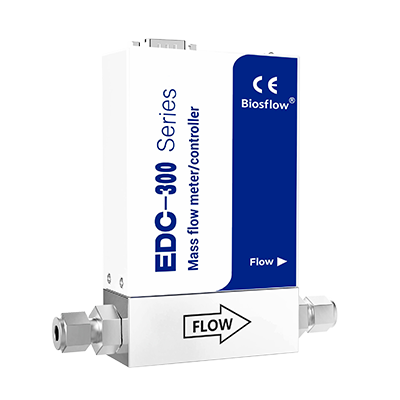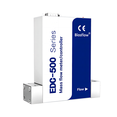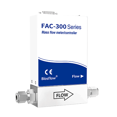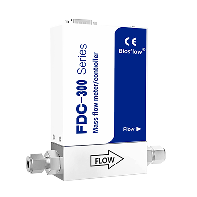
In fields such as industrial automation, semiconductor manufacturing, vacuum coating, photovoltaics, petrochemicals, and laboratories, the precise measurement and control of gas or liquid flow is often critical to the success of a process. To meet the needs of various applications, the industry has developed two core types of equipment: the Mass Flow Controller (mfc) and the Mass Flow Meter (mfm). They may look similar, but their functions are very different. An MFC can both measure and control gas flow. An MFM, on the other hand, only measures flow – it doesn’t control it. This fundamental distinction determines their respective roles within a system and guides the selection process.

MFC: An Integrated Solution for Measurement, Control, and Flow Stabilization
Best mass flow controllers feature a built-in closed-loop control valve and a PID control algorithm. They measure flow in real-time. They also automatically adjust the valve opening based on the user-defined setpoint. This ensures that the actual flow stabilizes quickly and precisely at that value. Even when system pressure or ambient temperature fluctuates, the MFC automatically compensates. This keeps the flow rate constant. In effect, it functions as an intelligent flow-stabilizing device. It combines measurement, control, and stabilization into a single unit.
Its control core relies on the PID (Proportional-Integral-Derivative) algorithm, with the three components working in concert:
Proportional (P): Responds immediately to the deviation; the larger the deviation, the stronger the corrective action, though steady-state error may persist.
Integral (I): Accumulates historical deviation and continuously eliminates residual error to ensure the flow precisely meets the target. However, excessive integration can lead to overshoot.
Derivative (D): Predicts flow trends and applies “braking” as the flow approaches the target value to suppress oscillation and overshoot; however, it is sensitive to noise and requires careful configuration.
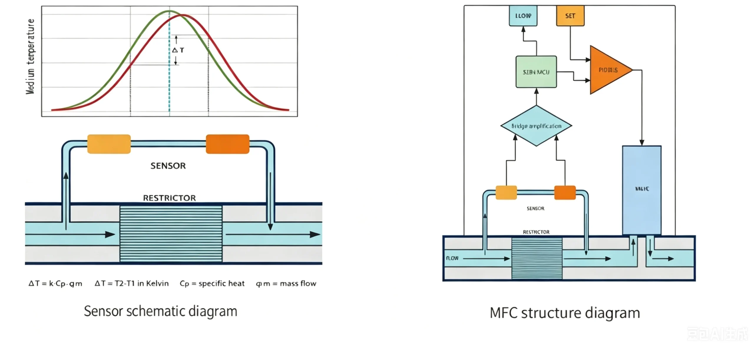
Gas mass flow measurement principles primarily include thermal (based on thermal diffusion) and differential pressure (based on laminar flow elements) methods.
Thermal air mass flow controllers measure mass flow. They are not affected by changes in temperature or pressure. That makes them the dominant choice for gas control applications.
There are two control valve options: normally closed and normally open. Normally closed valves close when power is lost – this is for safety. Normally open valves open when power is lost, and they are used for specific processes. The choice between them depends on your safety requirements.
Mass flow controllers find wide use in processes that require precise flow regulation. Examples include Chemical Vapor Deposition (CVD), Physical Vapor Deposition (PVD), Atomic Layer Deposition (ALD), plasma etching, ion implantation, fuel cell testing, and gas distribution systems.
MFM: For Precise Measurement Only
Mfm mass flow meter share the same sensors and signal processing units as mfc mass flow but lack control valves and PID regulation modules. These devices serve solely to measure the real-time mass flow rate of gases or liquids in a pipeline. They output the measured values as standard electrical signals (e.g., 4–20 mA, 0–5 V) or digital signals (e.g., RS485, EtherCAT) to a host computer or control system.
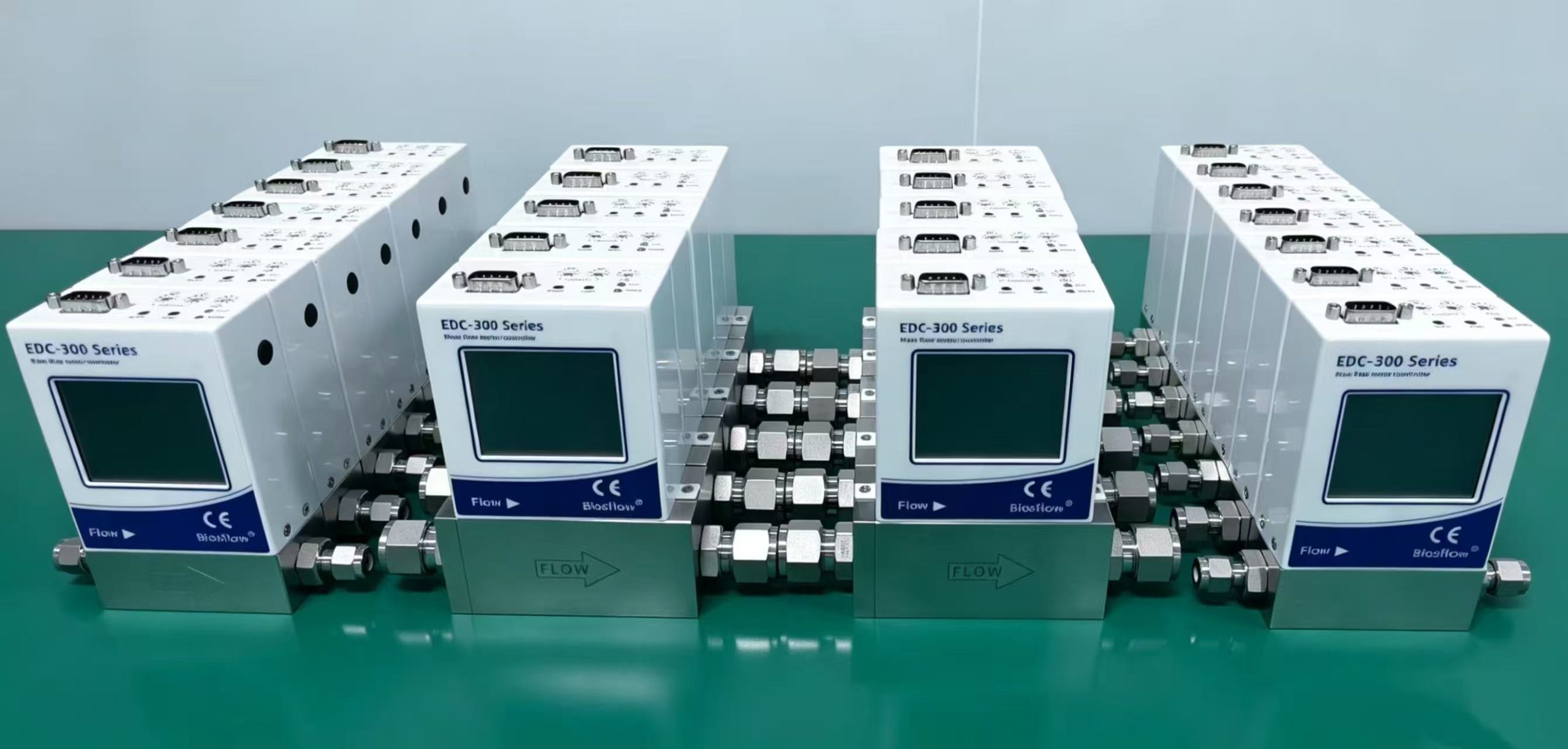
Mfm mass flow meters have no regulation functions. As a result, their structure is relatively simple. This leads to lower costs and reduced maintenance needs. Their measurement accuracy and repeatability are comparable to those of the best mass flow controllers. They are also unaffected by changes in temperature and pressure. Therefore, they are ideal for applications that require flow monitoring but not active control. Typical applications include flow metering in main gas supply lines, consumption tracking across process stages, gas leak detection, laboratory data acquisition, and use as reference meters for calibrating other flow equipment.
Shared Functions and Data Logging
Biosflow’s massflow controller and mfm mass flow meter units are equipped with displays that show PV, SV, and cumulative flow values.
PV (Process Value): The actual instantaneous flow rate currently detected.
SV (Set Value): The target flow rate desired by the user.
Users issue commands to the controller via a rotary knob, analog signals (0–5 V/4–20 mA), or communication interfaces (RS-485/Profibus).
Cumulative Flow Value: The total volume or mass that has flowed through the device since a specific starting point (usually the last reset or device power-up).
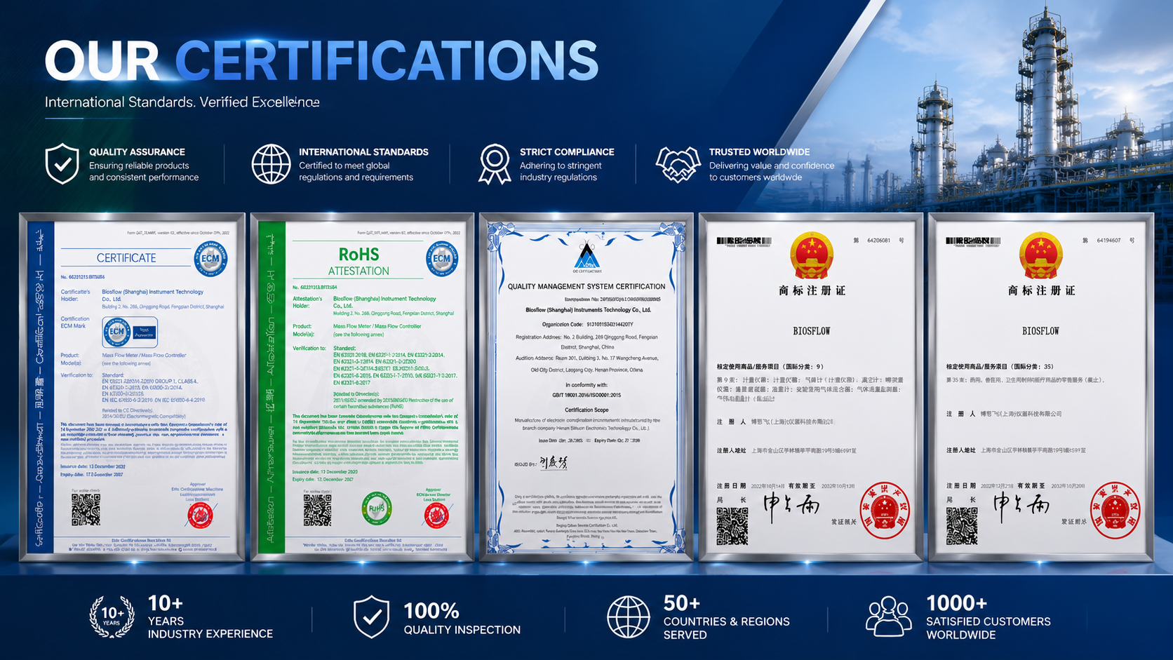
Additionally, these devices typically support various communication protocols (such as Modbus, Profibus, and DeviceNet), facilitating integration into automation systems for remote monitoring and parameter adjustment. Our products also hold various certifications, including CE, RoHS, and QMSC.
Selection Advice: Choose a mass flow controller if you require stable control of process flow; choose an mfm mass flow meter if you only need flow monitoring, as it offers a more cost-effective solution.
If you have any questions or need more detailed answers, please feel free to contact our sales manager alexa@biosflows.com.
Contact Us
Related Products